
How Thermal Expansion Affects Pipe Integrity During Expander Use
The physics of linear thermal expansion in common piping materials (steel, copper, PVC)
Piping materials all tend to expand when temperatures rise and shrink when they drop, following a basic principle described by the equation ΔL = αLΔT (which basically means change in length equals expansion coefficient multiplied by original length multiplied by temperature change). Different materials behave quite differently though. Steel grows about 0.0000065 inches for every inch of pipe per degree Fahrenheit increase. Copper isn't far behind at around 0.0000090 inches per inch per degree. But look at PVC it jumps to roughly 0.00003 inches per inch per degree, making it almost five times as stretchy as steel. To put this into perspective, imagine a 100 foot long steel pipe getting heated up 150 degrees Fahrenheit. It would actually grow close to 1.2 inches longer. The same length of PVC pipe under similar conditions would expand well over 5.4 inches. These differences create serious stress points wherever different materials meet. This becomes particularly problematic during operations involving expanders since local heat buildup amplifies these movements. The resulting forces can sometimes reach levels above 20,000 pounds, which is no small matter for engineers designing piping systems.
Why uncontrolled expansion creates stress, misalignment, and joint failure near expander zones
When thermal movement is restricted, pipes exert extreme force on anchors, flanges, and joints. Near expanders—where cyclic heating and cooling concentrate mechanical and thermal loads—three failure modes predominate:
- Stress concentration at bends and welds, surpassing yield strength
- Angular misalignment of flanges, leading to gasket blowouts
- Bell joint separation in push-fit systems, causing leaks
According to a recent study by the Ponemon Institute from 2023, about two thirds of all pipe failures in industrial facilities actually come down to poor management of thermal stress issues. When pipes experience repeated cycles of heating and cooling, this leads to faster fatigue development. The problem gets worse in areas where pipes are either anchored too tightly or not supported properly enough. For instance, when there's too much compression force on thin walled tubes, they tend to buckle. On the flip side, tension forces can cause cracks to spread through brittle materials like PVC. If piping isn't adequately supported, these stresses don't just stay local. They travel right through to other equipment components such as valves, pumps, and various instruments. This creates serious risks for what engineers call catastrophic flange failures. Even standard rated systems might fail completely at surprisingly low pressure levels around 740 psi when subjected to these uncontrolled forces over time.
Proper Expander Selection and Installation Best Practices
Matching Expander Type and Force Profile to Pipe Material and Wall Thickness
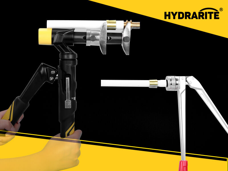
Choosing an appropriate expander really comes down to matching how much force it applies with what the pipe can handle mechanically. Steel pipes have much higher tensile strength compared to copper or PVC materials so they can take more radial expansion force. But don't forget about wall thickness either because that plays a huge role in all this. For those thin walled HVAC systems or lighter industrial piping applications, we generally need to keep expansion ratios low to prevent problems like buckling or ovalization issues. Speaking of materials, PVC gets pretty brittle when temperatures drop below 40 degrees Fahrenheit (which is about 4 Celsius). Using pneumatic expanders over 800 psi with PVC actually increases the chance of cracks spreading through the material. Copper behaves differently though since it's more ductile, allowing for greater displacement without damage when using mechanical expanders. When working on any project, make sure to check several things together: the specific grade of pipe material being used, its wall schedule details, and whatever torque specs the manufacturer recommends. This becomes especially important around welded joints where leftover stresses from welding can make pipes deform more easily under pressure.
Avoiding Over-Expansion: Calculating Safe Displacement Limits per ASME B31.1/B31.9
Over-expansion remains a leading cause of joint failure in pressurized systems. ASME B31.1 (Power Piping) and B31.9 (Building Services Piping) define maximum allowable expansion based on material, temperature, and geometry. Calibrating expanders to these limits ensures deformation stays within the elastic range and avoids permanent set or microcracking:
| Pipe Material | Max. Allowable Expansion (%) | Critical Threshold (ΔL/L) |
|---|---|---|
| Schedule 40 Steel | ±6% | 0.05 (at 300°F/149°C) |
| Type L Copper | ±9% | 0.07 (at 200°F/93°C) |
| PVC 80 | ±4% | 0.03 (at 120°F/49°C) |
Post-expansion verification is essential: laser profilometry should confirm internal diameter (ID) remains within ±0.5% of nominal. Deviations beyond this threshold increase leak risk under cyclic thermal loads.
Support and Anchoring Strategies to Protect Pipes Around Expanders
Strategic placement of anchors, guides, and sliding supports to absorb expander-induced movement
Good support systems actually handle thermal movement throughout the entire process of using expanders, not merely acting as passive restraints but actively distributing forces across the system. Anchors take on the pressure thrust and stop any axial movement at those fixed points. Guides limit sideways movement while still allowing for some forward/backward motion. Sliding supports are there to handle expected displacement through their low friction surfaces, usually placed around 4 to 10 pipe diameters away from joints and expansion areas. These three components work together pretty well to address the main problems engineers see on site: stress buildup at weld points, joints that get out of alignment, and pipes that buckle sideways under pressure.
Getting placement right requires looking at thermal expansion rates along with how the whole system is laid out instead of going with rough estimates for spacing. Primary supports are there to stop things from sagging and keep everything lined up when dealing with the weight of components themselves. Secondary supports do their part by reducing vibrations and keeping those annoying resonant frequencies in check. Those isolation liners inside clamping hardware serve a real purpose too they stop metal parts from rubbing against each other directly, which lets things move freely along the axis while still controlling the forces generated by expansion. For fixed points where absolutely no movement is acceptable like pump inlets or valve flanges we use non adjustable supports that lock everything down tight. But sometimes adjustments are needed on site, so manufacturers make versions that can be tweaked without hurting overall performance. Industry experience shows that when all these elements work together properly, mechanical and thermal stresses get spread out across the entire setup. This kind of engineering approach has been proven to extend equipment lifespan significantly, with maintenance records showing improvements of around 70% over time.
FAQs
What is the significance of thermal expansion in piping systems?
Thermal expansion plays a critical role in piping systems, as it can cause pipes to expand or contract significantly with temperature changes, leading to stress points, misalignment, and potential structural failures.
Why is PVC more susceptible to thermal expansion compared to steel?
PVC has a higher thermal expansion coefficient compared to steel, making it expand nearly five times more under the same temperature change. This can result in more pronounced expansion effects in PVC, particularly in high-temperature conditions.
What are some methods to mitigate the effects of thermal expansion in pipes?
Proper expander selection, matching the expander type to pipe material and wall thickness, and strategic placement of support and anchoring systems are key methods to manage and mitigate thermal expansion effects.
How can over-expansion be avoided in pressurized systems?
By adhering to guidelines like ASME B31.1/B31.9, and calibrating expanders to defined material and temperature limits, over-expansion can be avoided, ensuring deformation remains in the elastic range.