
 EN
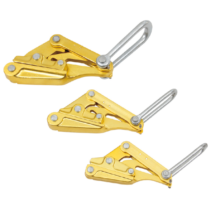
The Mechanical Principle Behind Every Cable Grip
A cable pulling grip does its work through a mechanism that is elegant in its simplicity and unforgiving when misapplied. The grip consists of a woven mesh of high-tensile wire strands, typically galvanized or stainless steel, formed into a tubular sleeve that slides over the end of a cable. At one end, the mesh is gathered into a pulling eye that attaches to the draw line, the fish tape, or the pulling winch. When tension is applied to that eye, the mesh elongates, and as it elongates, its diameter shrinks. The shrinking mesh compresses radially around the cable jacket with a force proportional to the pulling tension. The harder the crew pulls, the tighter the grip squeezes. This self-tightening action, often called the Chinese finger trap principle, is what allows a properly sized and installed grip to hold a cable weighing hundreds or thousands of pounds without any adhesive, clamp, or mechanical fastener touching the jacket. The holding force is distributed along the entire length of the mesh that is in contact with the cable. The longer the engagement length, the larger the surface area over which the compressive force is spread, and the lower the pressure at any single point on the jacket. This distribution is the key to maximum grip without damage. When the engagement is too short, the compressive force concentrates in a narrow band, deforming the insulation, cold-flowing the jacket material, or crushing the underlying conductors. When the grip is correctly sized and fully seated, the cable jacket experiences a uniform, distributed compression that holds the cable securely without exceeding the jacket's mechanical limits. Understanding this principle is the foundation of every grip selection decision that follows.
Grip Type Selection and the Variety of Cable Configurations
Cable pulling grips are not one-size-fits-all devices. The variety of cable types, pulling configurations, and job site conditions has produced a corresponding variety of grip designs, each optimized for a specific application. The most common distinction is between the closed mesh grip and the open mesh or split mesh grip. A closed mesh grip slides over the end of a cable and is used for a single pull from one end of a conduit run to the other. The cable is cut to length, the grip is installed, the pull is made, and the grip is removed at the far end. An open mesh or lace-up grip wraps around the cable at an intermediate point along its length and is used when the pull must be made in segments or when the cable cannot be fed from the end. The open design allows the grip to be installed and removed without access to a cable end. Beyond these basic categories, specialized grips address specific cable constructions. A grip designed for twisted pair or triplex service drop cable incorporates a flexible, conforming mesh that accommodates the non-circular cross-section without creating pressure points on the individual conductors. A grip for armored or interlocked cable uses a heavier gauge wire in the mesh to withstand the abrasion of the metallic jacket and to prevent the mesh strands from catching on the armor profile. A grip for fiber optic cable is a particularly sensitive application. The glass fibers cannot tolerate the compressive forces that a standard power cable grip generates. Fiber optic pulling grips often incorporate an integrated pulling eye that attaches to the cable's strength members rather than relying solely on radial compression of the outer jacket. A mesh grip used on fiber optic cable is typically a support device that manages the cable's weight during installation rather than a primary pulling device that transmits the full pulling tension through the jacket.
Sizing the Grip and the Critical Relationship to Cable Diameter
Every cable pulling grip is designed for a specific range of cable outside diameters. Selecting a grip whose diameter range does not match the cable is the most common and most damaging error in grip usage. An oversized grip, one whose minimum effective diameter is larger than the cable, will never achieve the mesh elongation and radial compression required to lock onto the jacket. The grip will slip under load, the mesh will slide along the jacket surface, and the friction-generated heat can melt or abrade the jacket before the crew realizes the grip is not holding. An undersized grip, one whose maximum effective diameter is smaller than the cable, cannot be installed without forcing it over the jacket or cutting away mesh strands, both of which compromise the grip's structural integrity and create stress concentrations that will tear during the pull. The correct grip fits snugly onto the cable when the mesh is in its relaxed state, slides on with firm hand pressure but without requiring tools, and has enough length that when the mesh elongates under tension, the compressed portion remains fully within the parallel body section of the grip rather than transitioning into the tapered eye section. Measuring the cable's outside diameter accurately is a prerequisite to grip selection. A caliper measurement taken at the actual pulling end, not a nominal diameter from a catalog, confirms that the cable falls within the grip's specified range. For cables that are not perfectly round, the grip must accommodate the widest cross-sectional dimension without exceeding its maximum rated diameter.
Installation Technique and the Factors That Determine Grip Security
A correctly sized grip installed incorrectly will fail as surely as the wrong grip for the job. The installation process begins with preparing the cable end. The jacket should be clean, dry, and free of any lubricant, dirt, or moisture that would reduce the friction between the mesh and the jacket surface. A grip installed over a lubricated cable jacket defeats the self-tightening mechanism at its foundation. The grip is slid onto the cable until the pulling eye section is past the cable end and the mesh extends far enough along the jacket that the full engagement length is achieved. How far is enough depends on the grip design and the cable diameter, but a practical guideline is that the mesh should extend onto the cable well past the point where the tapered transition from the eye to the cylindrical body ends. Once the grip is positioned, the trailing end of the mesh is secured to the cable. This step prevents the grip from peeling back or relaxing when tension is momentarily reduced during the pull. The most common securing method is to wrap a layer of vinyl electrical tape over the last few inches of the mesh and onto the cable jacket. This tape is not a load-bearing element. It is a positioning aid that keeps the mesh in contact with the jacket during the initial tensioning phase. For critical pulls, a hose clamp or a cable tie tightened gently over the tape and mesh adds a mechanical backup to the tape. The pulling eye is then connected to the draw line through a swivel, a component that is often overlooked but essential. The swivel allows the cable to rotate freely as it navigates bends in the conduit without twisting the grip, the draw line, or the cable itself. A pull without a swivel can twist the grip off the cable end or spiral the conductors into a bundle that jams inside the conduit.
Inspection, Wear Patterns, and Knowing When to Retire a Grip
Cable pulling grips are consumable items with a finite service life, not permanent tools that can be used indefinitely. The high-tensile wire mesh that gives the grip its strength is subject to wear every time it is installed, tensioned, and removed. A grip that has successfully completed dozens of pulls may look serviceable on casual inspection but harbor broken strands, stretched sections, or corrosion damage that will fail under the next load. Every grip should be inspected before every use. The inspection begins with the mesh. Run the grip through gloved hands, feeling for broken wire strands that will catch on the glove or on skin. A single broken strand changes the load distribution in the mesh and creates a sharp point that can score the cable jacket. Look for sections where the mesh has stretched or deformed, indicated by a change in the weave pattern or a section that no longer returns to its original shape when relaxed. Stretched mesh indicates that the grip has been overloaded beyond its elastic limit at some point in its history, and its residual strength is unknown. Examine the pulling eye and the fitting where the mesh terminates into the eye. This is the point of highest stress concentration, and cracks in the eye fitting or broken strands where the mesh enters the crimp or the swage are indicators of imminent failure. Check for corrosion on galvanized steel grips, particularly if the grip has been used outdoors or stored in damp conditions. Rust pitting reduces the effective cross-section of the wire strands and creates stress risers that initiate cracks. A grip that exhibits any of these conditions, broken strands, permanent mesh deformation, cracked eye fittings, or significant corrosion, should be removed from service and replaced. The cost of replacing a grip that might have had a few more pulls left in it is trivial compared to the cost of a grip failure that damages a cable requiring a full replacement pull.
Manufacturing Quality and the Supply Chain Behind Reliable Cable Grips
The holding force of a cable pulling grip, the self-tightening mechanism that converts pulling tension into radial compression, depends entirely on the quality of the wire mesh and the precision of its assembly. The wire itself must be drawn to a consistent tensile strength, with a diameter tolerance that ensures every strand in the weave carries an equal share of the load. The weaving process must produce a mesh with uniform strand spacing and consistent crossover angles, because variations in the weave pattern create local stress concentrations that weaken the grip at specific points. The termination of the mesh into the pulling eye, whether by swaging, crimping, or welding, must preserve the full strength of the wire bundle without introducing nicks, cuts, or heat damage that degrade the wire's mechanical properties. Hydrarite manufactures cable pulling grips with attention to these manufacturing fundamentals, producing grips where the mesh consistency, the termination integrity, and the dimensional accuracy align with the rated capacity marked on the fitting. For an electrical contractor, the reliability of a pulling grip translates into a predictable pulling operation. A grip that performs to its rated capacity, inspected and installed according to a disciplined procedure, allows the crew to focus on the pull itself rather than worrying about whether the grip will hold. That confidence is built on the manufacturing quality of the grip, proven over repeated pulls, and reinforced every time a grip comes out of the conduit still securely attached to the cable it was asked to deliver. The grip is a small component of the total cable installation project, but its performance determines whether the project is completed on schedule or interrupted by a failure that costs time, material, and reputation.
Table of Contents
- The Mechanical Principle Behind Every Cable Grip
- Grip Type Selection and the Variety of Cable Configurations
- Sizing the Grip and the Critical Relationship to Cable Diameter
- Installation Technique and the Factors That Determine Grip Security
- Inspection, Wear Patterns, and Knowing When to Retire a Grip
- Manufacturing Quality and the Supply Chain Behind Reliable Cable Grips